
A technical explainer for IoT professionals who need to understand mobile core architecture — not marketing spin.
When IoT connectivity providers talk about “dual-core” and “multi-core” connectivity, they are not referring to processor cores inside a router or gateway. They are describing how the mobile network core infrastructure behind your cellular connection is architected — and this architecture has a direct impact on the reliability, continuity, and operational resilience of every device in your deployment.
This guide breaks down the terminology, explains what is actually happening at each layer, and gives you the technical grounding to evaluate connectivity claims properly.
What “Core” Means in Cellular Networks
In mobile telecommunications, the network is split into two fundamental domains.
The Radio Access Network (RAN) is the physical layer: cell towers, base stations, antennas, and the radio spectrum they use. This is what your SIM module connects to over the air. It handles the wireless link between a device and the nearest cell site.
The Mobile Core Network sits behind the RAN and provides the intelligence. This is where:
- SIM authentication and identity verification takes place
- IP addresses are assigned to devices
- Data sessions (known as PDN or PDU sessions) are created and maintained
- Traffic is routed through packet gateways to the internet or private networks
- Security policies, quality of service rules, and roaming agreements are enforced
- Subscriber and session state is managed
The core is not a single server or a building. In modern networks it is a distributed cluster of virtualised network functions running across carrier data centres, often spanning multiple physical locations.
If the radio network is the road surface, the core is the traffic management system that decides who is allowed to drive, where they can go, and how data flows between origin and destination.
For IoT deployments, the architecture of this core layer — how it is structured, where it runs, and what happens when parts of it fail — determines whether your devices maintain stable, continuous connectivity or periodically drop offline and need to re-establish their sessions from scratch.
How an IoT Device Establishes a Cellular Connection
Understanding the connection lifecycle is essential context for evaluating core architectures.
When a cellular IoT device powers up or enters coverage:
- The modem scans for available radio networks and selects a cell based on signal strength and network selection rules (PLMN selection)
- The device attaches to the local base station over the air interface
- The base station forwards signalling messages to the mobile core network
- The core authenticates the SIM — verifying that the device has a valid identity and is authorised to connect
- The core assigns an IP address (either from a public pool or a private APN range)
- A session context is created — this is a record inside the core that holds the state of the connection: the assigned IP, the routing path, QoS parameters, and the security context
- A data path is established through a packet gateway (called a PGW in 4G or UPF in 5G) which routes traffic onward to the internet or a private endpoint
That session context is the critical element. It represents the live state of the device’s connection within the core. If that context is lost — because the core platform fails, restarts, or becomes unreachable — the device is disconnected. It must then repeat the entire attach, authenticate, and session establishment process from the beginning.
For many IoT applications, this re-establishment process causes visible disruption: dropped MQTT connections, interrupted data streams, lost TCP sessions, changed IP addresses that break inbound access, and devices that may take minutes to fully recover — or in edge cases, fail to reattach without a manual reset.
Single-Core Architecture
The simplest and most common deployment model.
In a single-core architecture, your IoT SIM is provisioned against one mobile core platform. All authentication, session management, and traffic routing flows through a single set of core network functions — typically operated by one carrier or MVNO in one region.
If that core platform experiences an outage — whether due to a software failure, a planned maintenance window, a hardware fault, or a connectivity issue in the carrier’s data centre — every device depending on that core loses its session. Devices go offline, and they stay offline until the core recovers and each device individually reattaches.
For non-critical or delay-tolerant IoT applications (environmental sensors reporting hourly, for example), this may be acceptable. For infrastructure monitoring, energy systems, fleet tracking, medical devices, or any deployment where connectivity gaps have operational or commercial consequences, single-core architecture represents a straightforward single point of failure.
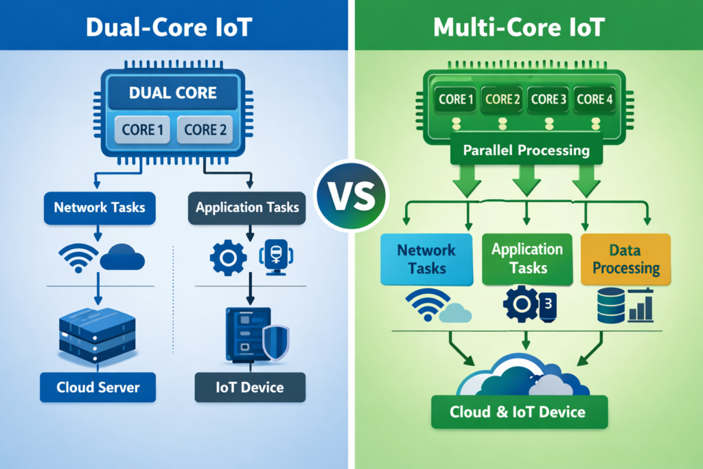
Dual-Core Connectivity
Dual-core connectivity introduces basic redundancy by providing two core platforms rather than one.
The typical model works as follows:
- Core A is designated as the primary. Devices attach to Core A under normal conditions, and all session state lives there.
- Core B is the secondary or standby core. It is available but not actively serving the device.
- If Core A fails or becomes unreachable, devices are expected to fail over to Core B.
What Actually Happens During a Dual-Core Failover
This is where the practical limitations become clear:
- Core A becomes unreachable
- The session context held in Core A is lost — there is no live replication to Core B
- The device detects that its connection has dropped (this detection itself can take seconds to minutes depending on modem firmware and keep-alive configuration)
- The device initiates a new attach procedure
- Core B authenticates the SIM and creates a fresh session context
- A new IP address is typically assigned
- Application-layer connections (MQTT, HTTPS, VPN tunnels, etc.) must be re-established from scratch
This is reactive redundancy. The system detects a failure and then recovers, but recovery is not instantaneous and it is not seamless. There is always a period of disconnection, and the new session is entirely independent of the old one.
Limitations of Dual-Core
Beyond the interruption during failover, there are structural constraints:
- The two cores are often operated by the same carrier or hosted in the same region, meaning certain classes of failure (regional network issues, backbone outages, DNS failures, routing problems) can affect both simultaneously
- Session state does not transfer between cores — every failover is a cold restart from the device’s perspective
- IP address changes during failover can break systems that rely on static or predictable addressing for inbound access, firewall rules, or allowlisting
- Application-layer reconnection logic must be robust enough to handle the disruption gracefully, which adds complexity to device firmware
Dual-core is meaningfully better than single-core. It reduces the probability of total loss of connectivity. But it does not eliminate disruption, and it does not provide session continuity.
Multi-Core Connectivity
Multi-core connectivity represents a fundamentally different architectural approach. Rather than designating one core as active and another as standby, a multi-core system distributes connectivity across multiple core instances, packet gateways, and transport paths — often spanning multiple carriers, regions, and backbone networks.
The design principles differ from dual-core in several important ways.
Distributed Session Intelligence
The most significant technical difference is how session state is handled.
In a dual-core model, session state exists in exactly one core at any given time. If that core fails, the state is gone.
In a multi-core architecture, session management is abstracted above the individual core instances. Session state can be replicated, synchronised, or managed through an overlay system that is not dependent on any single core remaining available. When a core instance fails or becomes degraded, the session management layer can reroute traffic through alternative core instances without requiring the device to re-authenticate or re-establish its session.
This is the difference between a system that recovers from failure and a system that absorbs failure without the device ever knowing it happened.
Multiple Concurrent Paths
Rather than a binary active/standby arrangement, multi-core systems maintain connectivity through a mesh of available paths. These can include:
- Multiple carrier core networks across different operators
- Geographically distributed packet gateways
- Regional points of presence that provide local breakout
- Private backbone transport between core instances (often using SD-WAN or MPLS technologies rather than the public internet)
If one path degrades or fails, traffic continues to flow through the remaining paths. The system does not wait for a failure event and then react — it continuously routes through the best available infrastructure.
IP and Session Continuity
Because the session management layer operates above individual core instances, multi-core architectures can preserve IP address assignments and active sessions through infrastructure failures. The device’s TCP connections, MQTT sessions, VPN tunnels, and application-layer state can remain intact even when underlying core components change.
This is particularly important for IoT devices that maintain persistent connections to cloud platforms, that receive inbound commands or configuration updates, or that operate behind NAT with port mappings that would break if the IP address changed.
Private Transport
Many multi-core implementations route traffic across private, controlled backbone networks rather than the public internet. This provides more predictable latency, avoids internet routing instability, and gives the connectivity provider direct control over path selection and failover behaviour. It also reduces exposure to DDoS attacks, BGP hijacking, and other internet-layer risks that can affect IoT traffic.
Key Terminology Reference
These terms appear frequently in discussions about core network architecture and IoT connectivity resilience.
Redundancy — having backup components available. Dual-core provides redundancy. Redundancy alone does not guarantee continuity.
Resilience — the ability to continue operating through faults without service interruption. Multi-core architectures aim for resilience, not just backup capability.
High Availability (HA) — a design target where uptime approaches 99.99% or higher. Achieving true HA requires distributed infrastructure with no single point of failure at any layer.
Session Continuity — maintaining active data sessions (TCP, UDP, application-layer) even when underlying network elements fail or change. This requires session state to be managed independently of any single core instance.
Packet Gateway (PGW / UPF) — the core network function that assigns IP addresses and routes user-plane traffic between the mobile network and external data networks. PGW is the 4G/LTE term; UPF (User Plane Function) is the 5G equivalent.
Private APN / DNN — a dedicated, isolated logical network segment within the mobile core. Traffic on a private APN is separated from public internet traffic and can have its own routing, security, and QoS policies. In 5G, this is called a Data Network Name (DNN).
Distributed Core — a core network architecture deployed across multiple data centres and regions, as opposed to being centralised in a single location.
Roaming Core — a core infrastructure that supports connectivity across multiple mobile operators, enabling devices to access different radio networks while maintaining a consistent core-layer experience.
Where eSIM and Multi-IMSI Fit
It is important to distinguish between identity-layer technologies and core infrastructure architecture, as they solve different problems.
eSIM (embedded SIM / eUICC) allows SIM profiles to be remotely provisioned, updated, or switched without physically changing the SIM card. This provides flexibility in choosing which operator identity a device presents to the network.
Multi-IMSI allows a single SIM to carry multiple operator identities (IMSIs), enabling the device to switch between operators — typically to access different radio networks in different regions or to fall back to an alternative operator if the primary has no coverage.
These technologies address radio-layer and identity-layer flexibility. They help a device connect to the best available radio network and present the right credentials to do so.
However, they do not inherently address core infrastructure resilience. A device with multi-IMSI capability that connects through a single-core backend still has a single point of failure at the core layer. The SIM can switch operator identities, but if all those identities route through the same core platform, the resilience benefit is limited to radio coverage — not infrastructure continuity.
The strongest connectivity architecture combines identity flexibility (eSIM or multi-IMSI for radio-layer resilience) with multi-core infrastructure (for core-layer resilience and session continuity). These are complementary layers, not alternatives.
A Layered Model for Evaluating IoT Connectivity
When assessing an IoT connectivity solution, it helps to think in layers and evaluate resilience at each one independently.
Layer 1 — Radio Access: Which networks can the device connect to? How many operators are available? Is coverage sufficient across all deployment locations?
Layer 2 — Identity: Can the device switch operator identities? Is eSIM or multi-IMSI supported? Can profiles be managed remotely?
Layer 3 — Core Infrastructure: How many core instances are involved? Is session state distributed or centralised? What happens to active sessions during a core failure?
Layer 4 — Transport Backbone: How does traffic move between the core and its destination? Is it routed over the public internet or a private backbone? Is path diversity built in?
Layer 5 — Application: Cloud platforms, device management, dashboards, APIs. These depend on every layer below them being stable.
Dual-core and multi-core are Layer 3 and Layer 4 design decisions. If these layers are weak, everything above becomes unstable — regardless of how good the radio coverage or SIM technology might be.
The Practical Difference
Dual-core connectivity gives you a spare engine. If the primary fails, the backup starts — but there is a gap while it warms up, and the vehicle has to pull over first.
Multi-core connectivity gives you a distributed power grid. If a generator trips offline, the grid continues supplying power through other paths. The lights do not flicker.
For IoT deployments where connectivity interruptions cause operational disruption, data loss, safety risk, or commercial cost — understanding this distinction is not academic. It determines whether cellular connectivity behaves as a reliable utility or as a system that occasionally needs recovery and intervention.
This is an independent technical explainer. It is not affiliated with or endorsed by any specific connectivity provider.